Project Development
Final Project : SMART SUNFLOWER SOLAR TRACKER
Final Project Concept:
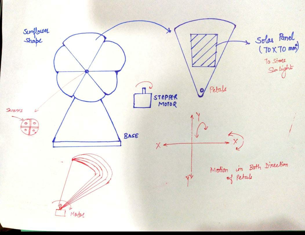
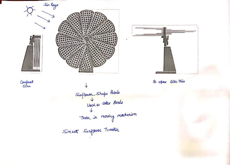
This project aims to capture maximum intensity in minimum possible space (flower shape) and rotate whole set of solar panel in sun moving direction so that efficiency can maximize. It tracks sun movement and changes its face toward sun just like sunflower
Smart sunflower solar tracker uses Nema-17 stepper motor with assistance of A4988 stepper driver to open up all the petals of sunflower which are folded initially with the help of Real Time clock module DS3231. Under this design, One Petal has its own motor which moved at the sunrise in the morning and rotate the whole set of petals. These characteristics make it a better fit for the irregularities and obstacles in tracking sun rays. Sunflower Petals having five solar panel mounted on it which moves from east to west direction and north to south direction .When Light Dependant Resistor(LDR) sensor got sufficient light in that direction. The motion in both the direction takes place with Metal Gear MG-90 Servo Motor.
Sketch Ideation
Final Project Process:
- 1. I have designed the petals on Solid Edge ST-09 and printed them on Stratasys F-370.
- 2. The support for Vertical and Horizontal Servo Motor designed on Solid Edge ST-09 and printed on stratasys F-370.
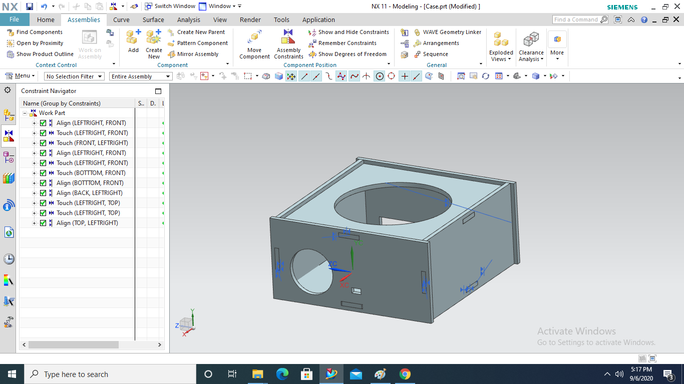
- 3. The box for Electronics designed on NX-11 and Laser Cut on SIL Laser cutting machine.
- 4. The Electronics has been designed on Eagle and milled on SRM-20.
- 5. The stepper will have to rotate at a particular time using Real Time Clock Module.
- 6. Servo motor will have to rotate using LDR.
Bill Of Materials (BOM)
| Description | Particular | Quantity | Unit Price(₹) | Unit Price($) | Total Price($) |
|---|---|---|---|---|---|
| Microcontroller | Atmega 328p AU | 2 | 111 | 1.51 | 3.02 |
| Resistor | 10k ohm | 6 | 2 | 0.027 | 0.162 |
| Resistor | 499 ohm | 2 | 1.5 | 0.020 | 0.04 |
| Capacitor | 100 nF | 4 | 1.45 | 0.020 | 0.080 |
| Capacitor | 1 uF | 2 | 3.88 | 0.053 | 0.106 |
| Capacitor | 10 uF | 4 | 3.5 | 0.054 | 0.216 |
| Capacitor | 22 pF | 4 | 1.02 | 0.014 | 0.056 |
| Crystal | 16 Mhz | 2 | 10 | 0.14 | 0.28 |
| LED Green | 1206 smd | 2 | 5 | 0.068 | 0.136 |
| LED Blue | 1206 smd | 1 | 5 | 0.068 | 0.068 |
| Switch | PushbUtton | 2 | 5 | 0.068 | 0.136 |
| RTC Module | ds3231 | 1 | 111 | 1.51 | 1.51 |
| Mini Solar Panel | 5V | 5 | 60 | 0.82 | 4.1 |
| LDR | 5V | 4 | 5 | 0.068 | 0.136 |
| Red Acrylic | 8ftx4ft | 1-sheet | 3000 | 40 | 40 |
| Yellow PLA Roll | Stratasys | 0.15 | 500 | 6.80 | 6.80 |
| White ABS Roll | Stratasys | 0.15 | 500 | 6.80 | 6.80 |
| Green ABS Roll | Stratasys | 0.05 | 300 | 4.08 | 4.08 |
| Electrolytic Capacitor | 1000uf | 2 | 24 | 0.33 | 0.66 |
| Ftdi Header | 12 | 10 | 0.014 | 0.014 | 0.14 |
| ISP Header | 6 pin | 10 | 0.014 | 0.14 | 0.14 |
| Stepper Driver | A4988 | 1 | 100 | 1.36 | 1.36 |
| SERVO Motor | MG995 | 1 | 350 | 4.76 | 9.52 | Stepper Motor | STP-43D1034 42 | 1 | 364 | 4.98 | 4.95 |
| Total Price- | $ 84.496 |
Computer Aided Design
Preliminary Design
This is the preliminary design for the petals and the animation showing how petals will move in one revolution of stepper motor.I do various iterations for design.So this animation was done on previous design.
This animation showing motion that need to be completed with Nema-17 Stepper Motor.
This animation showing the motion need to be done by Vertical Servo Motor.
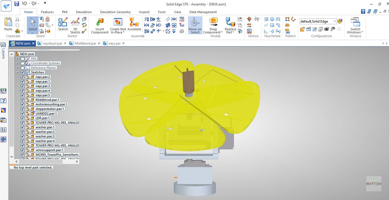
FINAL DESIGN
This is the final Design of Smart Sunflower Solar Tracker.I made 71*71mm slots for Mini Solar Panels to fit into the petals.I cut some material from petals as it will become heavy and will take extra material in 3D Printing.
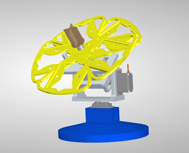
As for the motion of all the petals ,I made protrusion and slots in every petal so that if one petal move with stepper motor remaining will also move with them at an angle of 65 degree.
Here is the exploded View
Electronics Design
For Electronics Design first I tried my board for Rtc as input and stepper motor as output on Attiny 44.
After PCB milling and soldering when I tried the code on that PCB it shows library error for RTC.The documentation is available on my Output Devices Page.
Arduino: 1.8.13 Hourly Build 2020/03/16 09:33 (Windows 10), Board: "ATtiny24/44/84, ATtiny44, Internal 8 MHz"
  C:\Users\Afsha Rana\AppData\Local\Arduino15\packages\arduino\hardware\avr\1.8.3\libraries\Wire\src\utility\twi.c: In function 'twi_init':
  C:\Users\Afsha Rana\AppData\Local\Arduino15\packages\arduino\hardware\avr\1.8.3\libraries\Wire\src\utility\twi.c:88:16: error: 'SDA' undeclared (first use in this function); did you mean 'DDA0'?
     digitalWrite(SDA, 1);
                  ^~~
                  DDA0
  C:\Users\Afsha Rana\AppData\Local\Arduino15\packages\arduino\hardware\avr\1.8.3\libraries\Wire\src\utility\twi.c:307:53: error: 'TWIE' undeclared (first use in this function); did you mean 'TWEN'?
       TWCR = _BV(TWINT) | _BV(TWEA) | _BV(TWEN) | _BV(TWIE); // enable INTs, but not START
  C:\Users\Afsha Rana\AppData\Local\Arduino15\packages\arduino\hardware\avr\1.8.3\libraries\Wire\src\utility\twi.c:397:16: error: 'TWEN' undeclared (first use in this function); did you mean 'TWCR'?
       TWCR = _BV(TWEN) | _BV(TWIE) | _BV(TWINT) | _BV(TWEA);
  C:\Users\Afsha Rana\AppData\Local\Arduino15\packages\arduino\hardware\avr\1.8.3\libraries\Wire\src\utility\twi.c: In function 'twi_releaseBus':
  C:\Users\Afsha Rana\AppData\Local\Arduino15\packages\arduino\hardware\avr\1.8.3\libraries\Wire\src\utility\twi.c:444:3: error: 'TWCR' undeclared (first use in this function); did you mean 'EECR'?
     TWCR = _BV(TWEN) | _BV(TWIE) | _BV(TWEA) | _BV(TWINT);
     ^~~~
     EECR
  exit status 1
  Error compiling for board ATtiny24/44/84.
  This report would have more information with
  "Show verbose output during compilation"
  option enabled in File -> Preferences.
These are the error occured while programming. I thought RTC library didnot work on Attiny 44. I asked my instructor about it and they also suggested me that attiny 44 is not compatible with RTC and this made me to redesign it with ATmega 328p
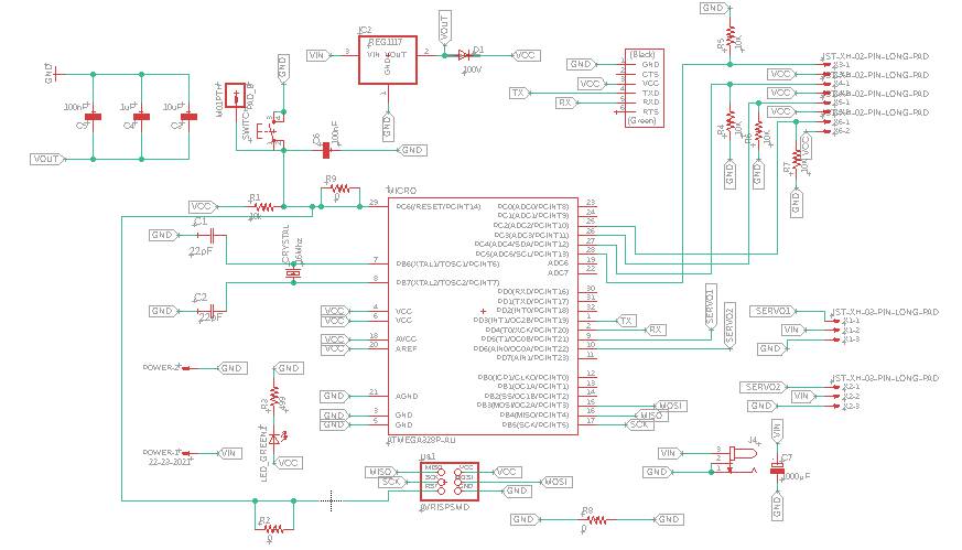
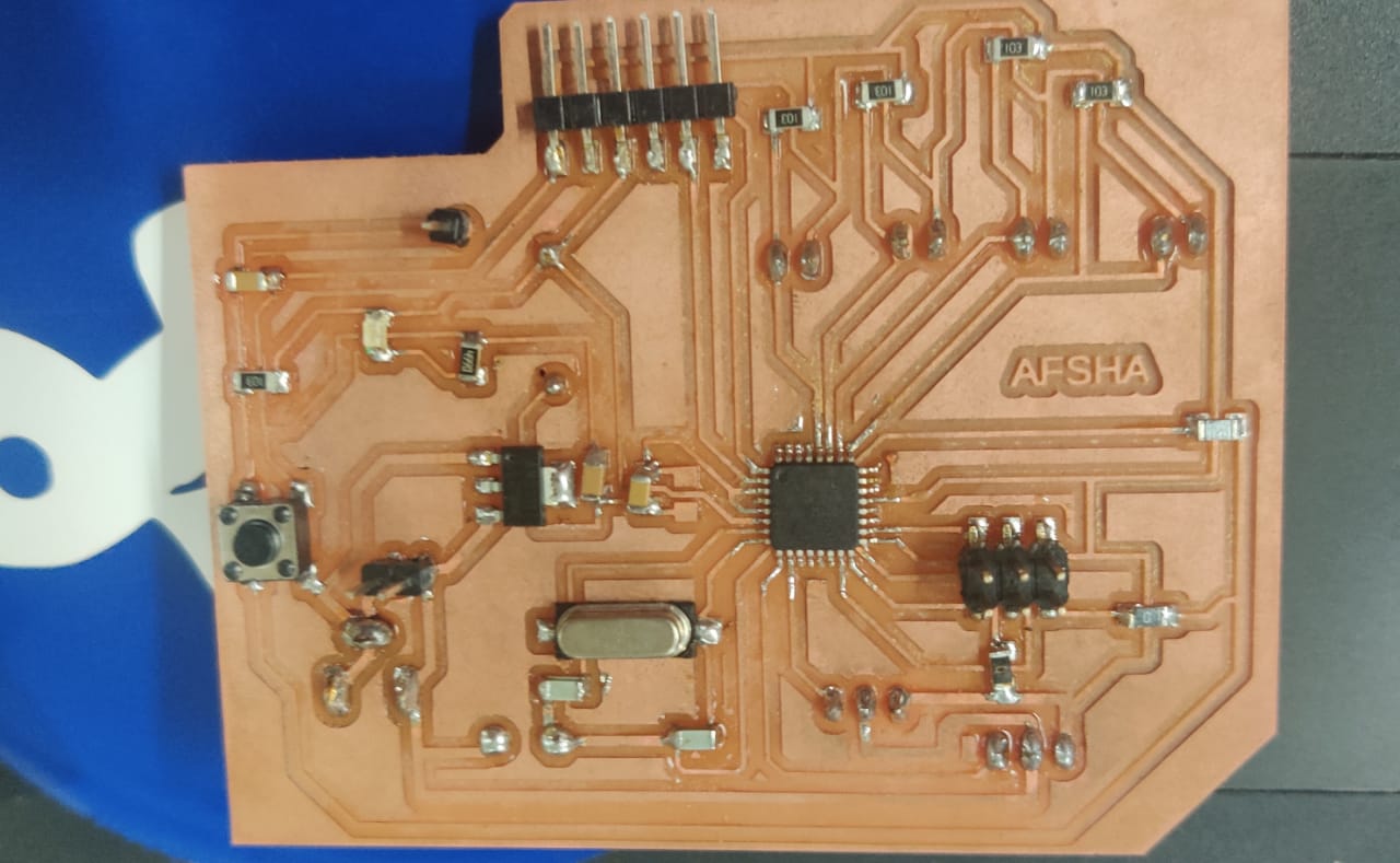
Then I moved to Atmega 328p for RTC and Stepper motor.The images below showing the Schematic and Board.I used jack to give power supply to board with 12V adapter.
BOARD FOR RTC AS INPUT AND STEPPER MOTOR AS OUTPUT
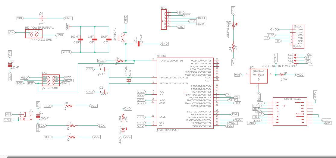
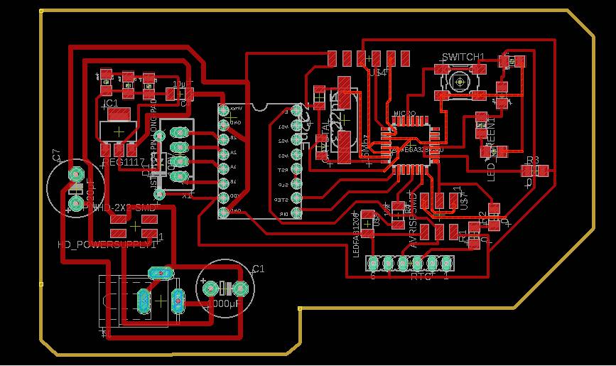
It is necessary to make VCC and GND track to be thick to withstand 12V and high ampere current.In my case, track width was 32 mill.5V voltage regulator was added to give 5V power to Microcontroller 328p.Traces for A4988 stepper Driver was mirrored as I want to soldered it from below.
As I want to use Step and Dir of microcontroller,I used pwm pins D5 and D6.Enable pin as MOSI.
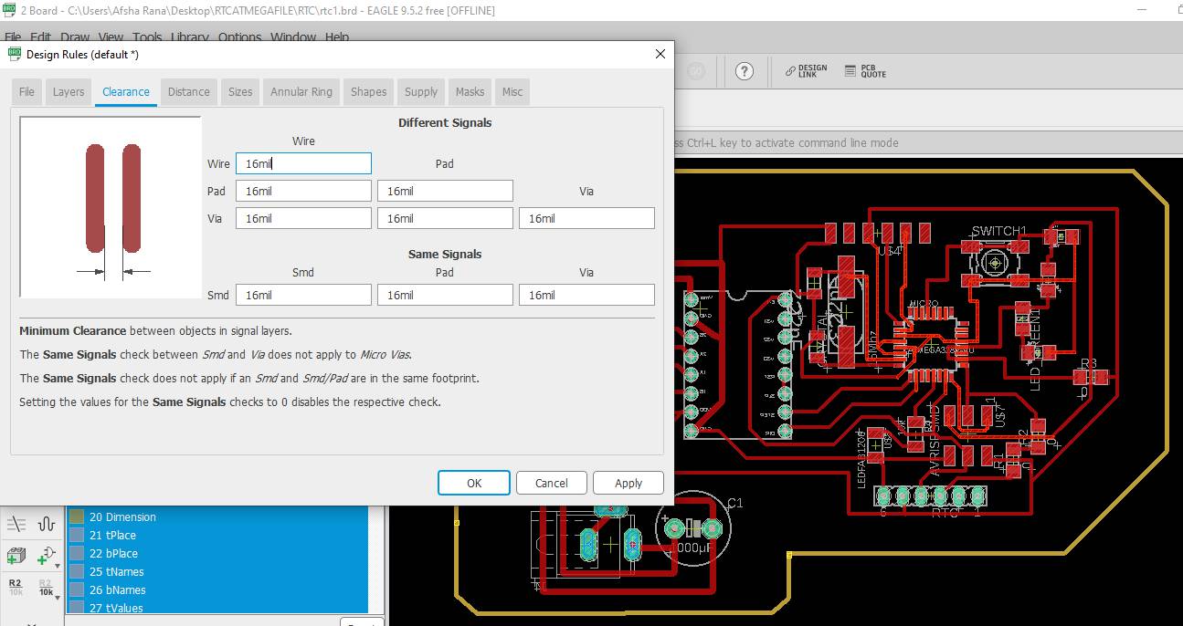
Design Rules are as follows:
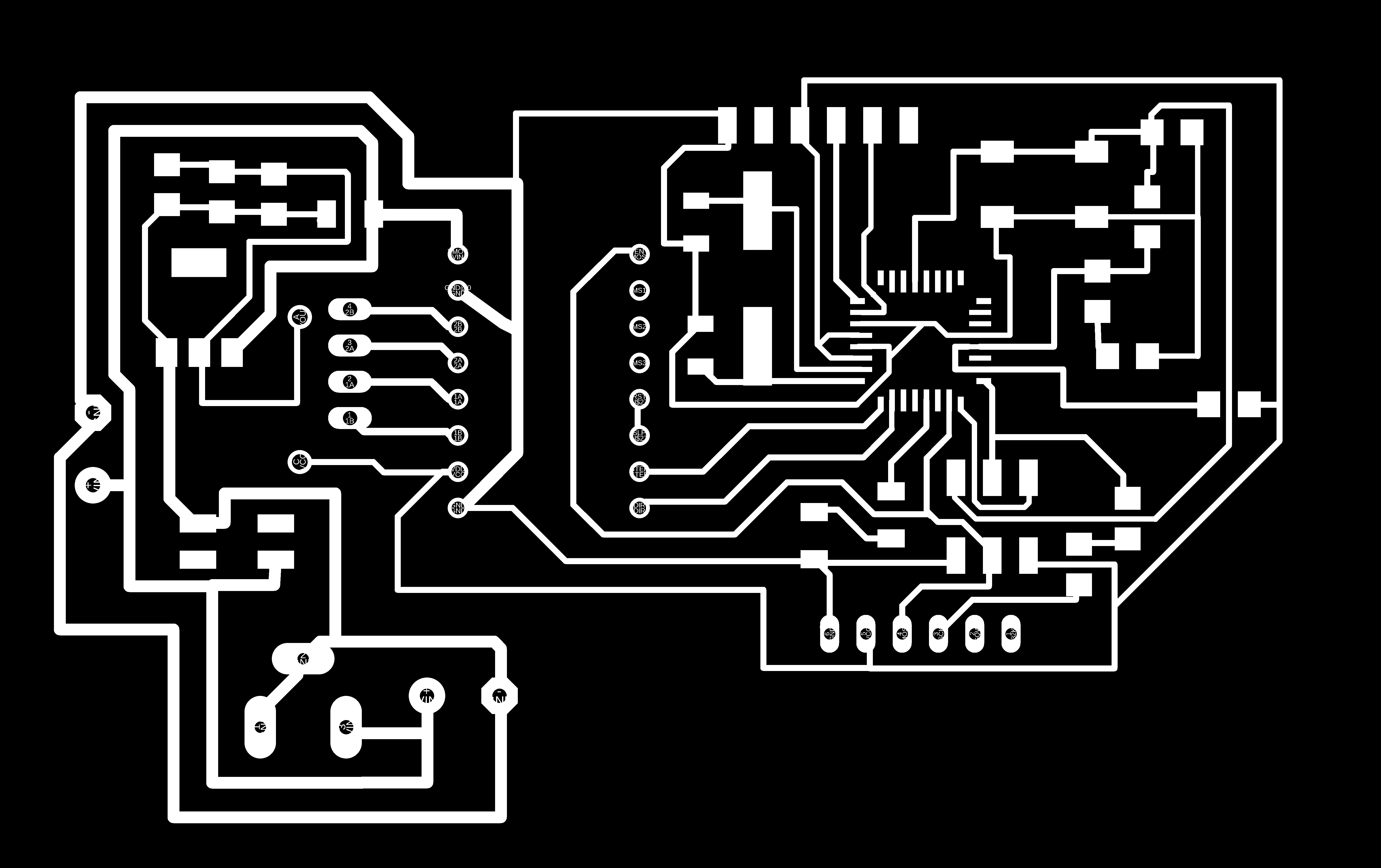
These are the PNG images exported in order to convert these files to rml file through FABmodules.This is the image exported while making traces and pads visible in layers and all other layers was hidden.

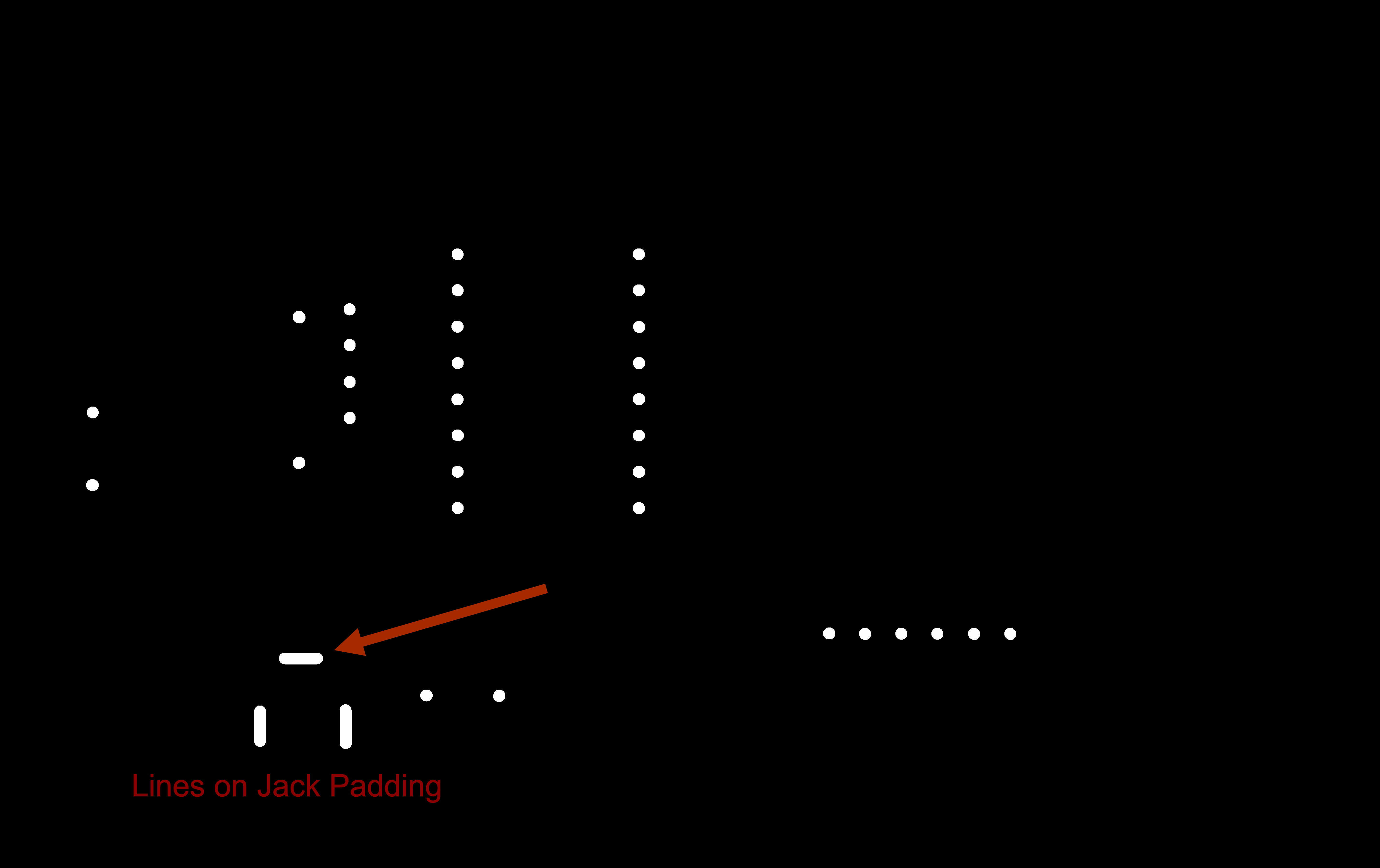
When the file for hole has to be upload on Fabmodule make sure to invert the image to get the actual hole instead of getting to be cut on outline of hole.
For Jack I made line on holes layer so that it will cut.
NOTE: While drilling holes invert the image in order to get exact holes,otherwise instead of getting holes of exact dimension the drill will cut the boundary and hole size will be 0.8mm more than the size of hole.
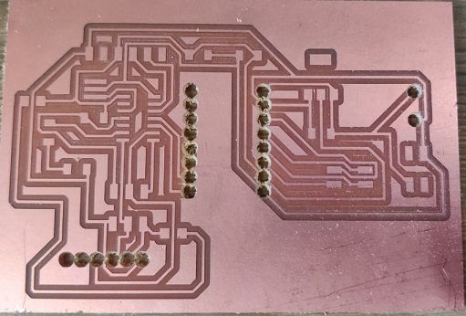
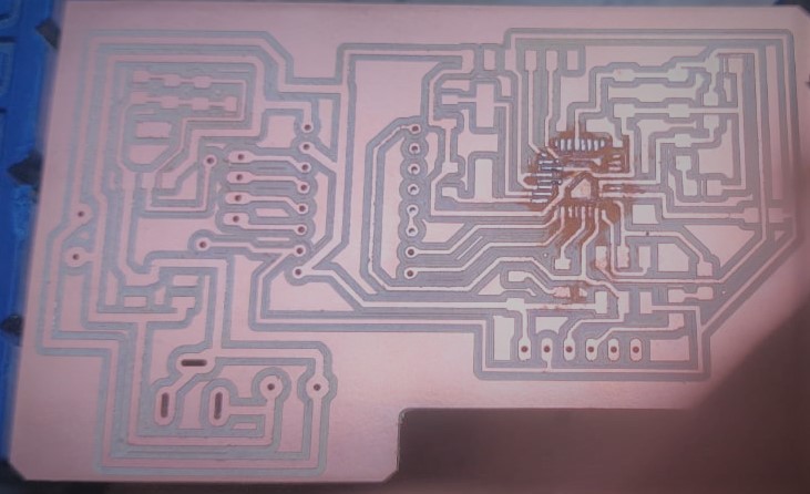
This is the example of one of my old PCB.
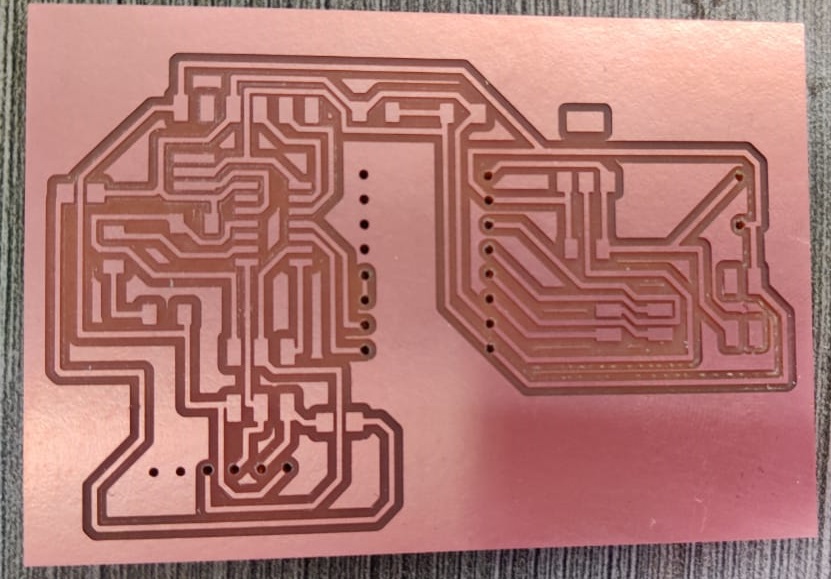
These are the corrected holes but in this there is also one error padding was missing
PNG File should be used like this.
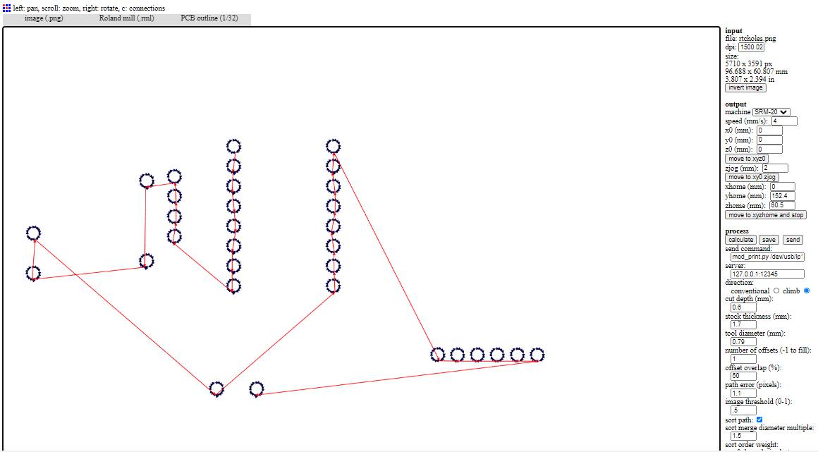
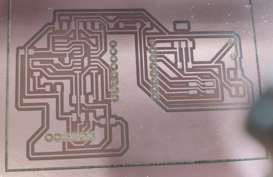
This tool path generated withuout inverting the image and results can be seen in image above. /P>
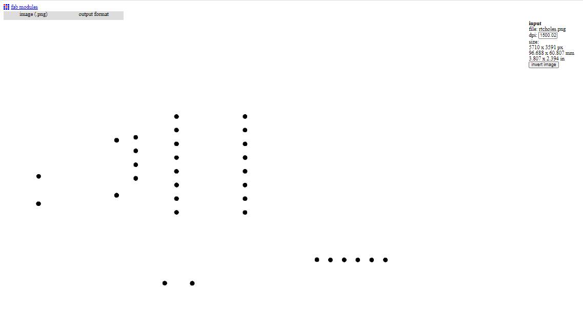
This is the inverted image where holes are black.Drill will remove this black dot only.
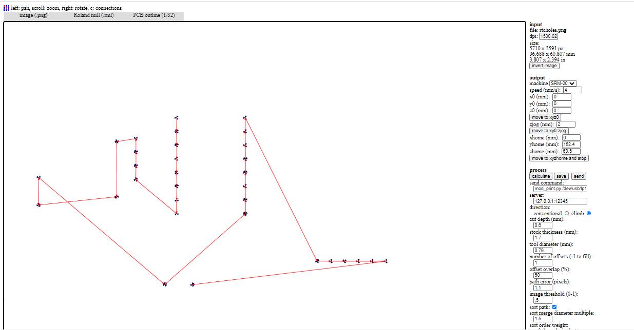
This is the correct tool path to drill holes.
STEPPER MOTOR PCB
The traces for this PCB comes out fine.
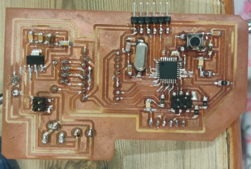
BOARD FOR LDR AS INPUT AND SERVO AS OUTPUT
I have also designed this board on Attiny 44 but when I uploaded the whole program of 4 LDR inputs and 2 servo motor. The memory of attiny was almost full.I was not able to see the data of serial monitor with that, then I had moved to Atmega 328P.

As per Shatshakit I implement my design on it.For burning bootloder I gave 16 MHz oscillator and two 22uf capacitors and also pins for AVRISP(MISO MOSI RST GND VCC SCK).After Voltage Regulator, I gave diode so that current does not come back again to it.


These are the PNG traces exported to go to milling process.
PCB MILLING
The process for PCB Milling was explained in Electronic Production week.
Here is the Video showing Milling of Final Baord PCB.
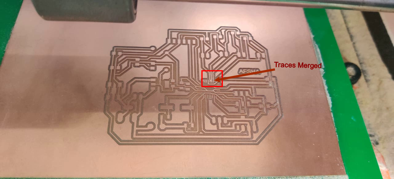
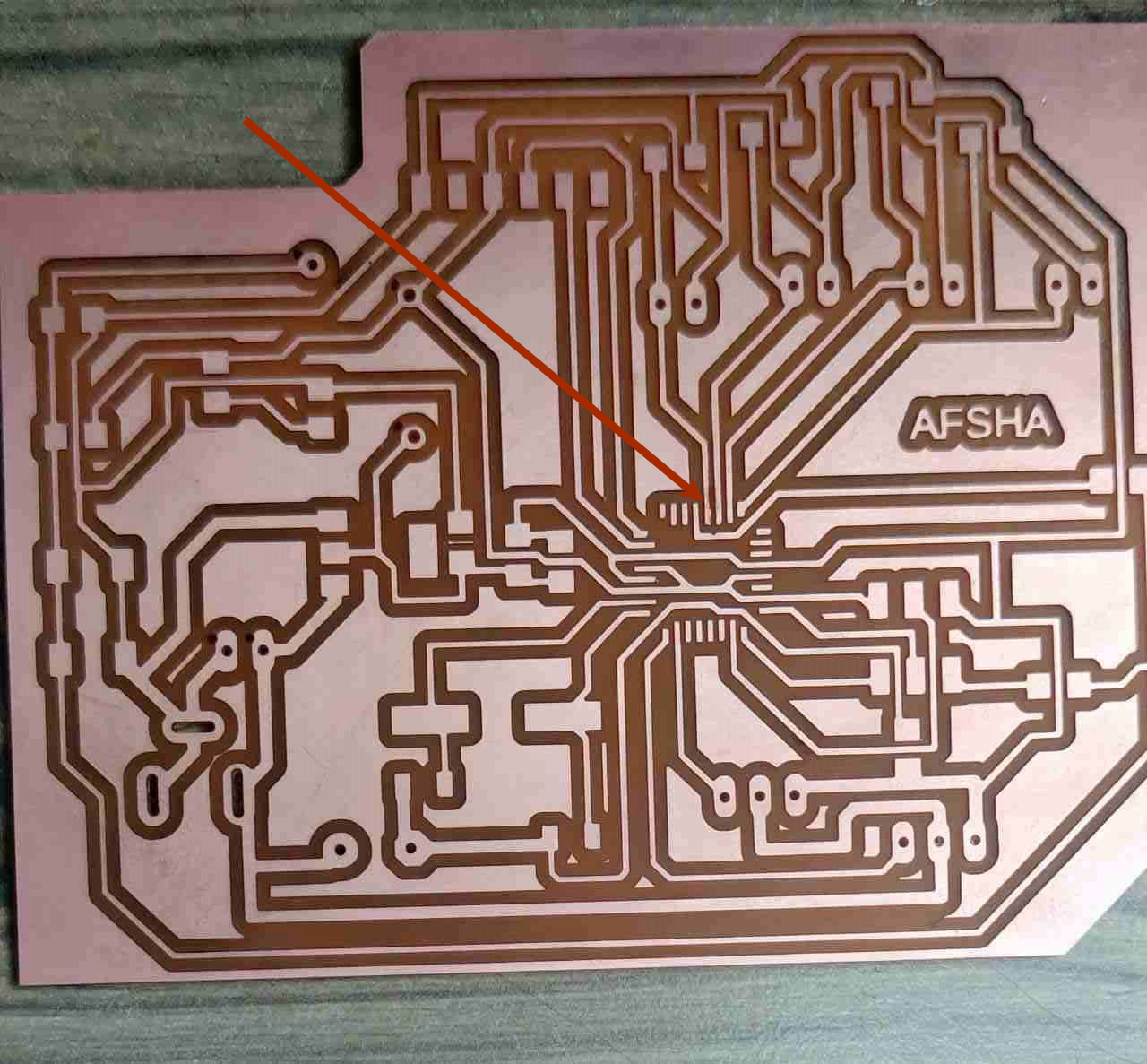
After Milling this is the PCB for Servo Motor and LDR.Everything come out fine except at one point on Atmega traces got shot.I used knife to cut the shot traces.
Soldering
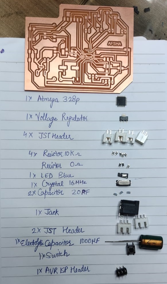
For soldering, I collect all the components and write it down.Below is the Image showing all the components.
Here is the video for soldering
After soldering the PCB is here.
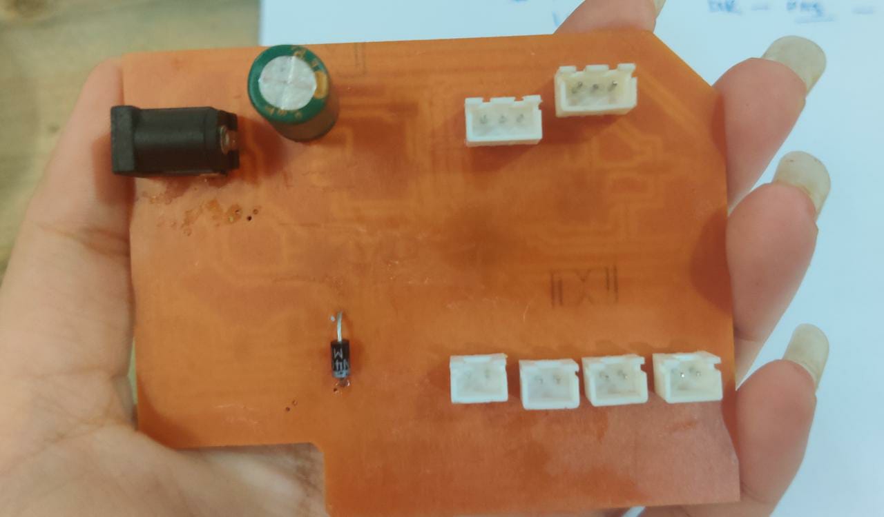
This is the backside of PCB.
The main problem I faced when I milled the holes of PCB without pad layer, It is very difficult to solder the header pins without padding.Remember to export top as well pad layer to mill traces of PCB.
First time I tried burning bootloader, it shown signature error. I changed the Atmega 328p ic and tadda second time the bootlaoder burnt.
STEPPER MOTOR PCB
This is the backside of PCB.
3D PRINTING
Initial Design Test Print
In this design I have printed petals one by one and shaft of motor differently on MakerBot, but the design fails as there was too much restrictions there while moving with hands only.Then I decided to change the design and results are Below:
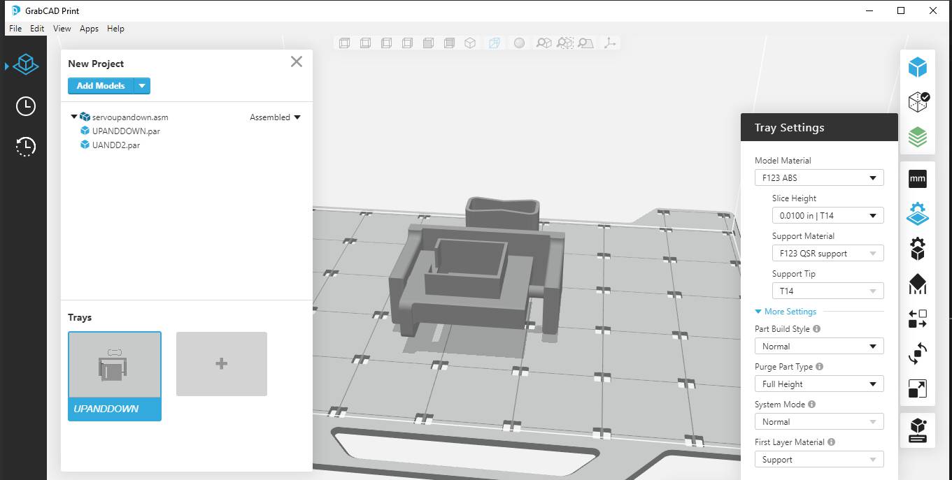
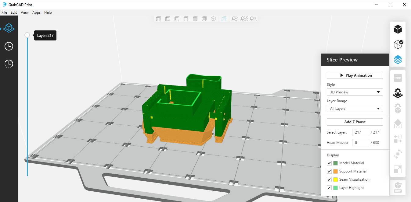
The petals of Smart Sunflower Solar Tracker was printed on Stratasys F-370. The strategy was made on GrabCAD Print.
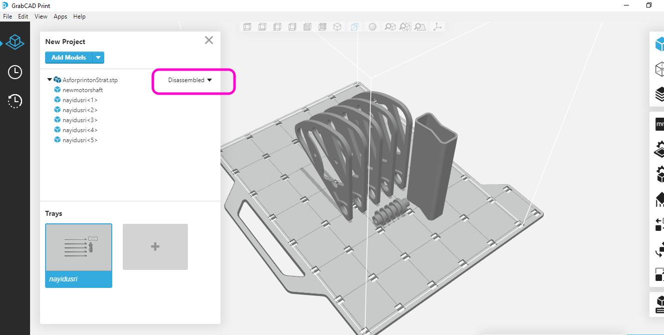
I have Exported the assembly of petals in SolidEdge to Stepfile and then imported it on GrabCAD Print Sofware.
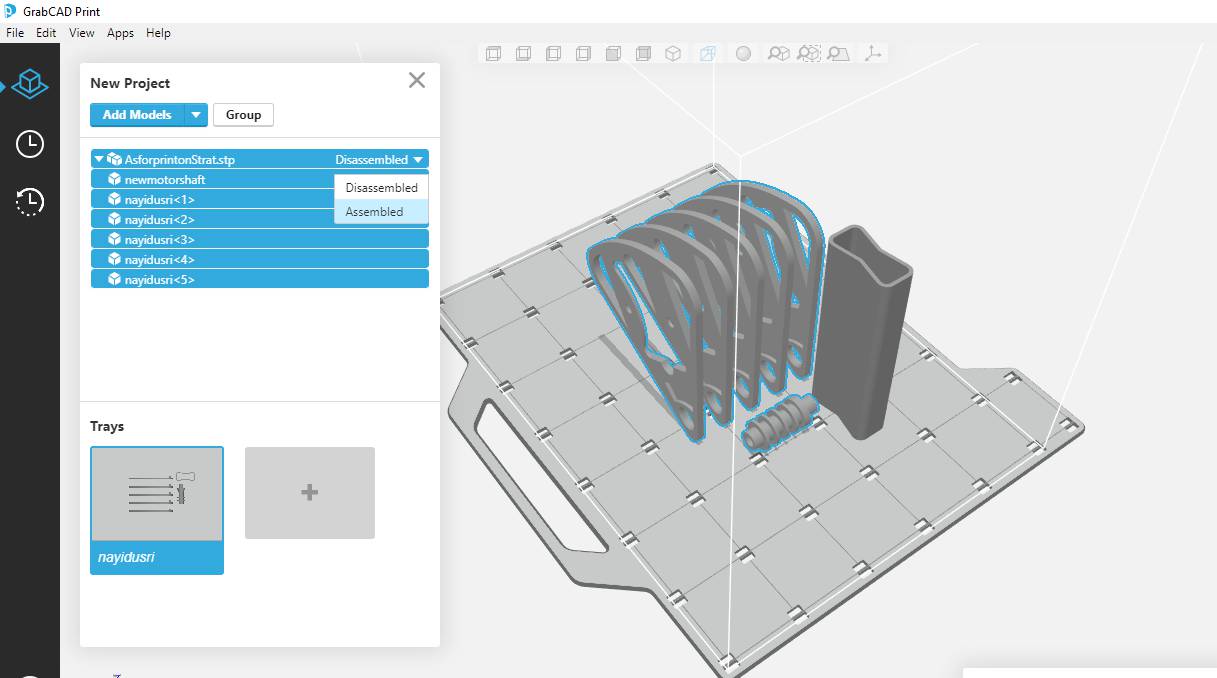
The assembled option was selected as I want to print the whole assembly in one go.
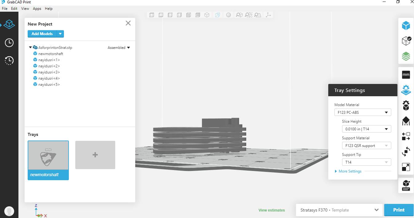
Material Selected was PC-ABS as there was some percent of leftover material was available in our Lab for the same. The layer height was 0.01 inches
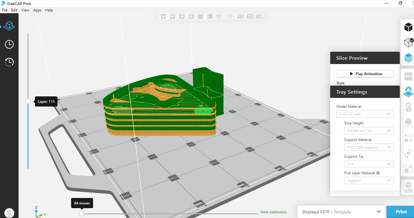
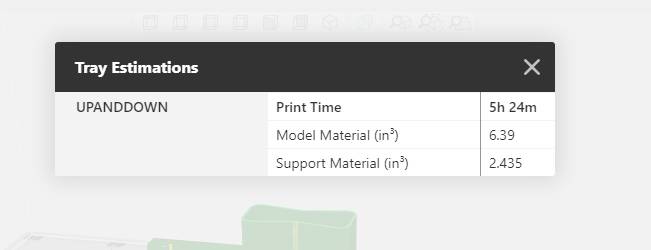
Printing time and volume of material and support used in inches cube shown in image below:
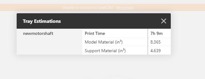
This is the final Printed part
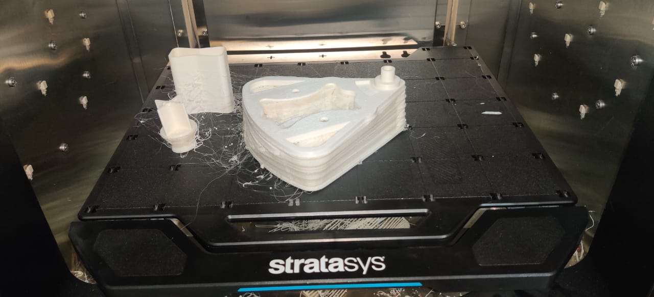
As support material was there,I Dipped it in Quick support removal solution of Stratasys which is patented solution includes chemical A and Chemical B soluble in 10 litre of water. This takes 8 hours to dissolve at 70 degree Celcius.
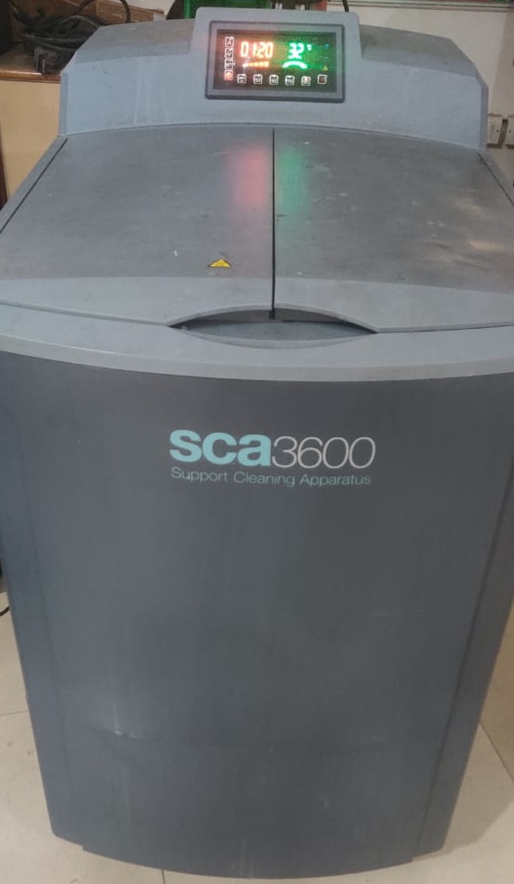
This is the quick support removal machine
 \
\
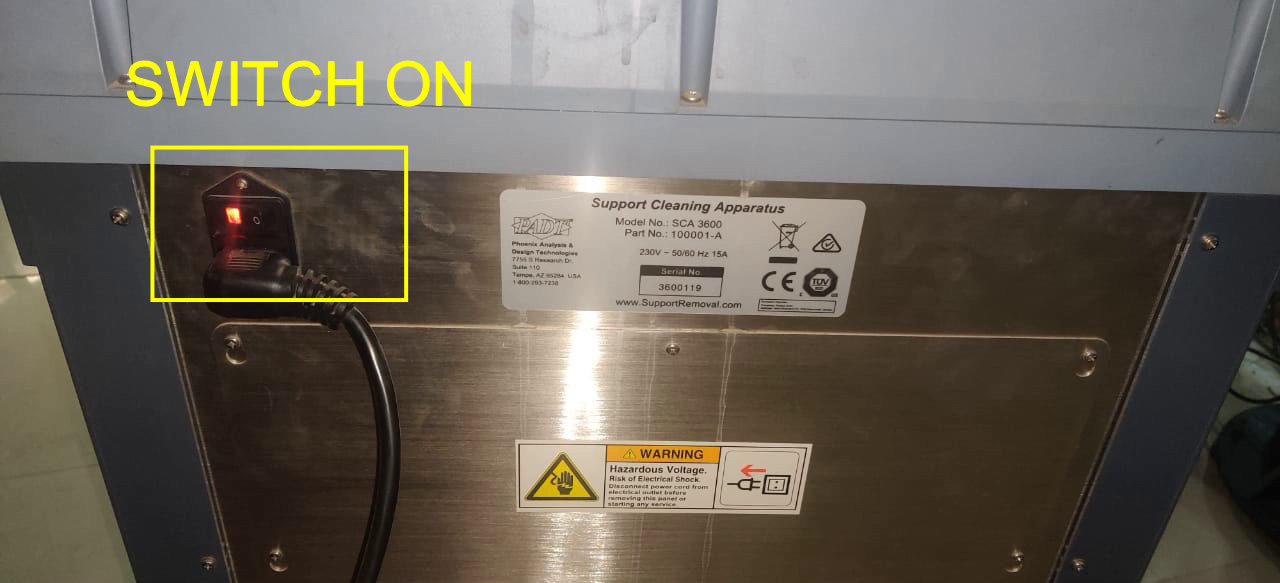
First you have to switched it ON from behind. The button is in image.
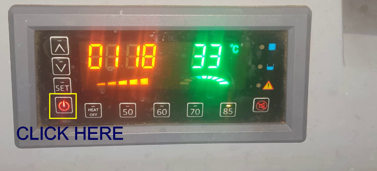
Now click on POWER button on this panel.You have to click on set to increase or decrease the duration for which you want to dip the part in it.Below are values for temperature according to material. I used PC-ABS thats why the temperature I set was 85 degree celcius.
 \
\
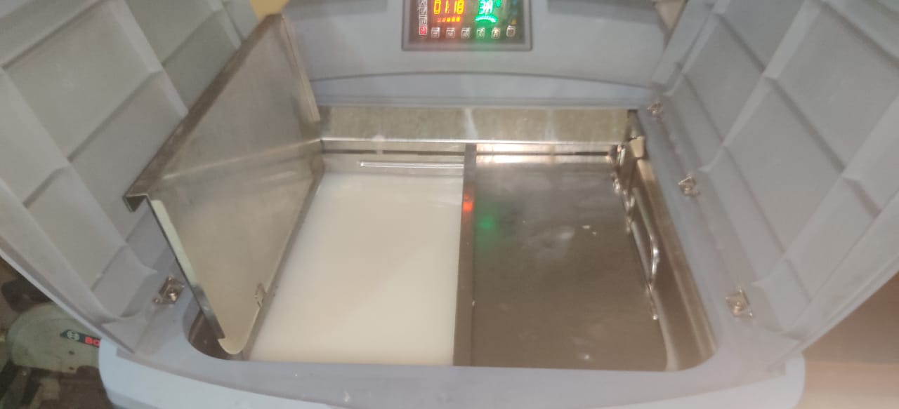
This is the bath tub of solution.
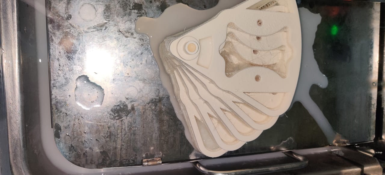
Here you can see model before I left it for removal.
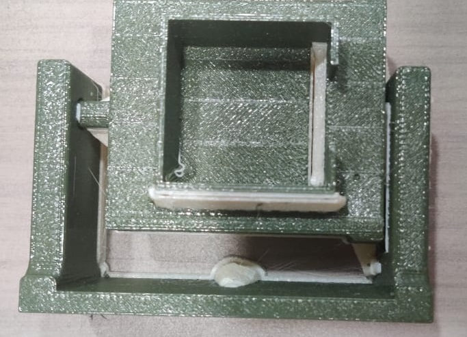
VERTICAL SERVO MOTOR AND STEPPER MOTOR SUPPORT
I printed this assembly for both vertical servo and stepper motor arrangement.
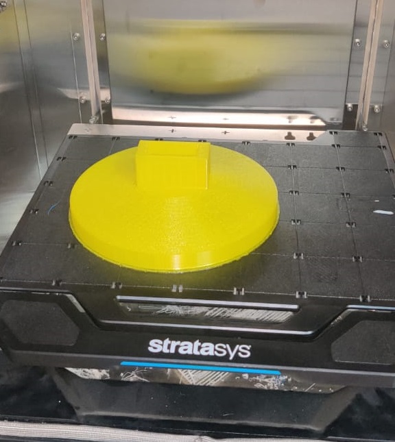
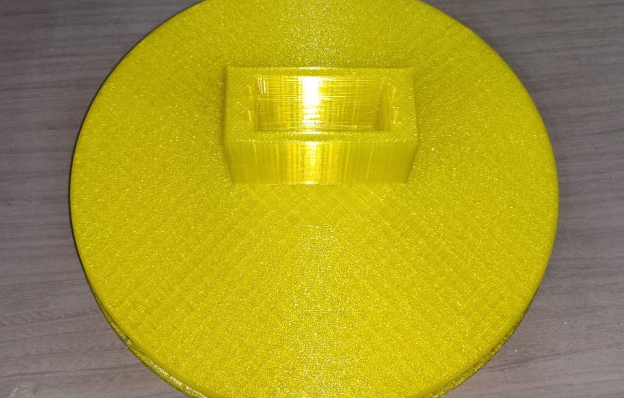
HORIZONTAL SERVO SUPPORT
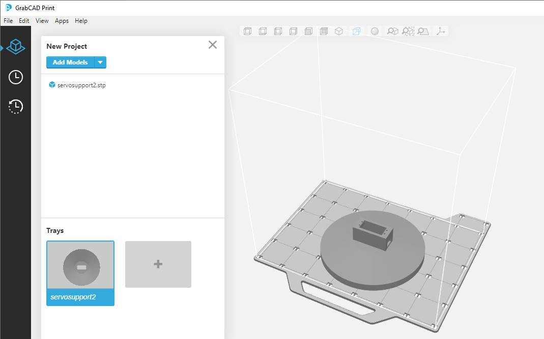
I printed the Base from Yellow PLA filament.
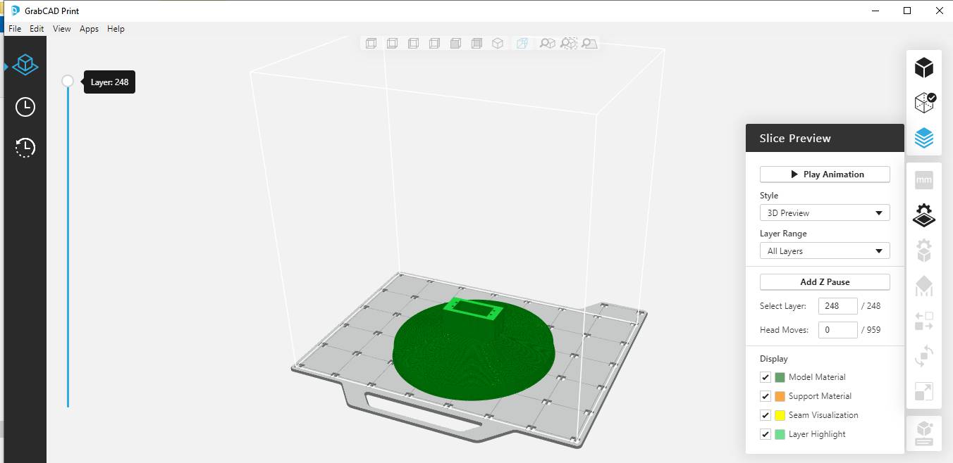
The layer height was 0.01 inches
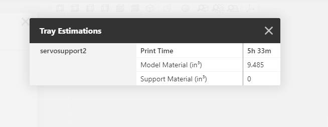
This is showing the material volume and time for print on Stratasys F-370
The support material is of the same material, I removed it manually.
STEPPER MOTOR TESTING
This is the testing of stepper motor with the petals mounted on it.
int x;

void setup()
{

  pinMode(11,OUTPUT); // Enable
  pinMode(5,OUTPUT); // Step
  pinMode(6,OUTPUT); // Dir
  digitalWrite(6,LOW); // Set Enable low
}

void loop()
{
  digitalWrite(11,HIGH); // Set Enable low
  digitalWrite(6,HIGH); // Set Dir high

  for(x = 0; x < 200; x++) // Loop 200 times
  {
    digitalWrite(5,HIGH); // Output high
    delayMicroseconds(2000); // Wait
    digitalWrite(5,LOW); // Output low
delayMicroseconds(2000);  }
    digitalWrite(11,HIGH); // Set Enable low
    digitalWrite(6,LOW); // Set Dir Low
  for(x = 0; x < 200; x++) // Loop 200 times
  {
    digitalWrite(5,HIGH); // Output high
delayMicroseconds(2000);
   digitalWrite(5,LOW); // Output low
delayMicroseconds(2000);
  }
  delay(300); // pause one second
}
In this code Step and Direction pin of stepper driver are output pins. If the Dir pin is high the shaft of stepper motor will move in clockwise direction and if the Dir is pinis low it will move in anticlockwise direction.Dir pin defines the direction of motor and step pin defines the step of motor.As motor moves in steps per revolution I have defined 200 steps per revolution and STEP pin needs to b high to run the motor and Enable pin needs to low.
SERVO MOTOR TESTING
This is the motion of horizontal servomotor assembled on 3D printed support.
  #include "Servo.h"

  Servo myservohorizontal;  // create servo object to control a servo
  // twelve servo objects can be created on most boards

  int pos = 0;    // variable to store the servo position

  void setup() {
    myservohorizontal.attach(5);  // attaches the servo on pin 9 to the servo object
  }

  void loop() {
    for (pos = 0; pos <= 180; pos += 1) { // goes from 0 degrees to 180 degrees
      // in steps of 1 degree
      myservohorizontal.write(pos);              // tell servo to go to position in variable 'pos'
      delay(15);                       // waits 15ms for the servo to reach the position
    }
    for (pos = 180; pos >= 0; pos -= 1) { // goes from 180 degrees to 0 degrees
      myservohorizontal.write(pos);              // tell servo to go to position in variable 'pos'
      delay(15);                       // waits 15ms for the servo to reach the position
    }
  }
This video showing motion of the vertical motor.
    #include "Servo.h"

    Servo myservovertical;  // create servo object to control a servo
    // twelve servo objects can be created on most boards

    int pos = 0;    // variable to store the servo position

    void setup() {
      myservovertical.attach(6);  // attaches the servo on pin 9 to the servo object
    }

    void loop() {
      for (pos = 0; pos <= 180; pos += 1) { // goes from 0 degrees to 180 degrees
        // in steps of 1 degree
        myservovertical.write(pos);              // tell servo to go to position in variable 'pos'
        delay(15);                       // waits 15ms for the servo to reach the position
      }
      for (pos = 180; pos >= 0; pos -= 1) { // goes from 180 degrees to 0 degrees
        myservovertical.write(pos);              // tell servo to go to position in variable 'pos'
        delay(15);                       // waits 15ms for the servo to reach the position
      }
    }
In this code for servo motor Servo.h library included.I defined two motor one is horizontal and other is vertical.We have to define pin number of motors by myservo.attach. We can give initial position by int position command.Void loop is used for running program continously and for command is used to define condition of position of motor.
LDR TESTING
This is the testing of LDR on PCB and serial monitor showing value of LDR.
I used FTDI to TTL convertor for Serial Communication and connected RX,TX and GND of ATmega FTDI which I used 3 and 4 pin to TX and RX GND of convertor.Programm to See data on Serial Monitor
    #include "SoftwareSerial.h"
    #define RX   4   //TX pin of ATmega
    #define TX    3  //RX pin of ATmega
    SoftwareSerial mySerial(4,3);  //RX, TX

    int sensorPin = A5; // select the input pin for LDR

    int sensorValue = 0; // variable to store the value coming from the sensor
    void setup() {
      mySerial.begin(9600); //sets serial port for communication
    }
    void loop() {
      sensorValue = analogRead(sensorPin); // read the value from the sensor
      mySerial.println(sensorValue); //prints the values coming from the sensor on the screen

      delay(1000);
    }
In this code LDR is defined at pin A5 of microcontroller and analogread is used to read the value of sensor and mySerial.pritln is used to see the data on serial monitor and my serial is defined for Rx and Tx to get the data from sensor.
RTC TESTING
This is the testing of RTC module showing current date and time on serial monitor.
Code
    #include "Wire.h"
    #include "RTClib.h"
    #include "SoftwareSerial.h"
    #define RX   4   //TX pin of ATmega
    #define TX    3  //RX pin of ATmega
    SoftwareSerial mySerial(4,3);  //RX, TX

    RTC_DS3231 rtc;

    char daysOfTheWeek[7][12] = {"Sunday", "Monday", "Tuesday", "Wednesday", "Thursday", "Friday", "Saturday"};

    void setup ()
    {
      mySerial.begin(9600);
      delay(3000); // wait for console opening

      if (! rtc.begin()) {
        mySerial.println("Couldn't find RTC");
        while (1);
      }

      if (rtc.lostPower()) {
        mySerial.println("RTC lost power, lets set the time!");

      // Comment out below lines once you set the date & time.
        // Following line sets the RTC to the date & time this sketch was compiled
        rtc.adjust(DateTime(F(__DATE__), F(__TIME__)));

        // Following line sets the RTC with an explicit date & time
        // for example to set January 27 2017 at 12:56 you would call:
        // rtc.adjust(DateTime(2017, 1, 27, 12, 56, 0));
      }
    }

    void loop ()
    {
        DateTime now = rtc.now();

        mySerial.println("Current Date & Time: ");
        mySerial.print(now.year(), DEC);
        mySerial.print('/');
        mySerial.print(now.month(), DEC);
        mySerial.print('/');
        mySerial.print(now.day(), DEC);
        mySerial.print(" (");
        mySerial.print(daysOfTheWeek[now.dayOfTheWeek()]);
        mySerial.print(") ");
        mySerial.print(now.hour(), DEC);
        mySerial.print(':');
        mySerial.print(now.minute(), DEC);
        mySerial.print(':');
        mySerial.print(now.second(), DEC);
        mySerial.println();

        mySerial.println("Unix Time: ");
        mySerial.print("elapsed ");
        mySerial.print(now.unixtime());
        mySerial.print(" seconds/");
        mySerial.print(now.unixtime() / 86400L);
        mySerial.println(" days since 1/1/1970");

        // calculate a date which is 7 days & 30 seconds into the future
        DateTime future (now + TimeSpan(7,0,0,30));

        mySerial.println("Future Date & Time (Now + 7days & 30s): ");
        mySerial.print(future.year(), DEC);
        mySerial.print('/');
        mySerial.print(future.month(), DEC);
        mySerial.print('/');
        mySerial.print(future.day(), DEC);
        mySerial.print(' ');
        mySerial.print(future.hour(), DEC);
        mySerial.print(':');
        mySerial.print(future.minute(), DEC);
        mySerial.print(':');
        mySerial.print(future.second(), DEC);
        mySerial.println();

        mySerial.println();
        delay(1000);
    }
Wire.h library for the I2C interface (included in Arduino IDE)
The function rtc.now() in our code returns a DateTime data type that contains the current date and time of the rtc.
To initialize the serial with a baud rate of 9600 bps, we will use the code Serial.begin(9600)
rtc.begin() is used to initialize the rtc object.
SERVO WITH LDR
Here is the video showing when I light up the LDR it turns the motor to 90 degree and when there is no light it moves to zero degree.
  #include "Servo.h"
  #include "SoftwareSerial.h"
  #define RX   4   //TX pin of ATmega
  #define TX    3  //RX pin of ATmega
  SoftwareSerial mySerial(4,3);  //RX, TX
  int val=0;// initialize variable val
  Servo myServo;
  void setup()
  {
  pinMode(A5,OUTPUT);// set digital pin 13 as “output”
  mySerial.begin(9600);   // set baud rate at “9600”
  myServo.attach(5);   // servo pin
  myServo.write(0);     // servo start position
  }
  /* The loop() function executes the program repeatedly until Specified. */
  void loop()
  {
  val=analogRead(A5);// read the analog value of the sensor and assign it to val
  mySerial.println(val);// display the value of val
  delay(10);// wait for 0.01
  if(val>150)
  {
     myServo.write(90);
  }
  else
  {
     myServo.write(0);
  }
  }
In this code as described above I set the value of ldr as 150 and above this value the servo motor start running and rotated 90 degree.
Laser Cut Box
The box was designed on NX-11 and here you can see the design :
These are the dxf file imported on RD Works and exported to laser cutting.
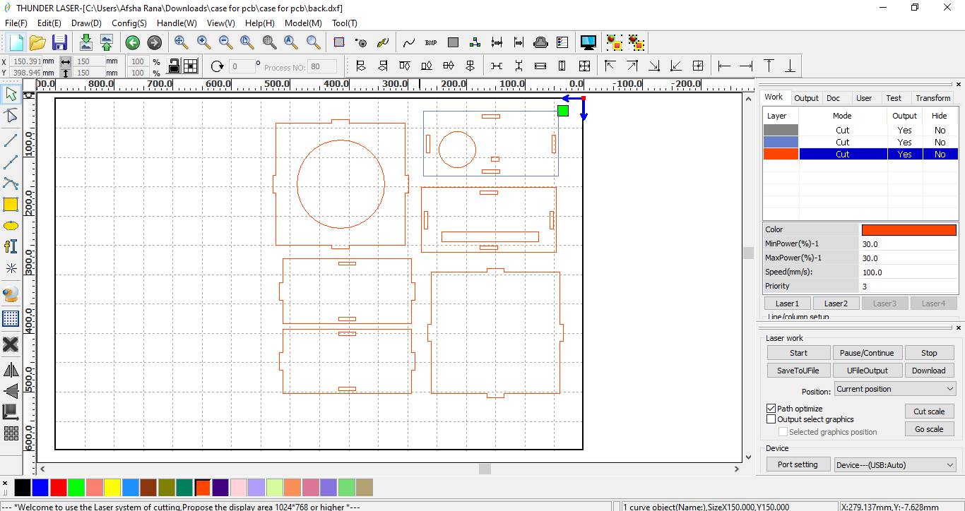
Laser Cutting into Action:
Here you can see cutting of each part of the block.
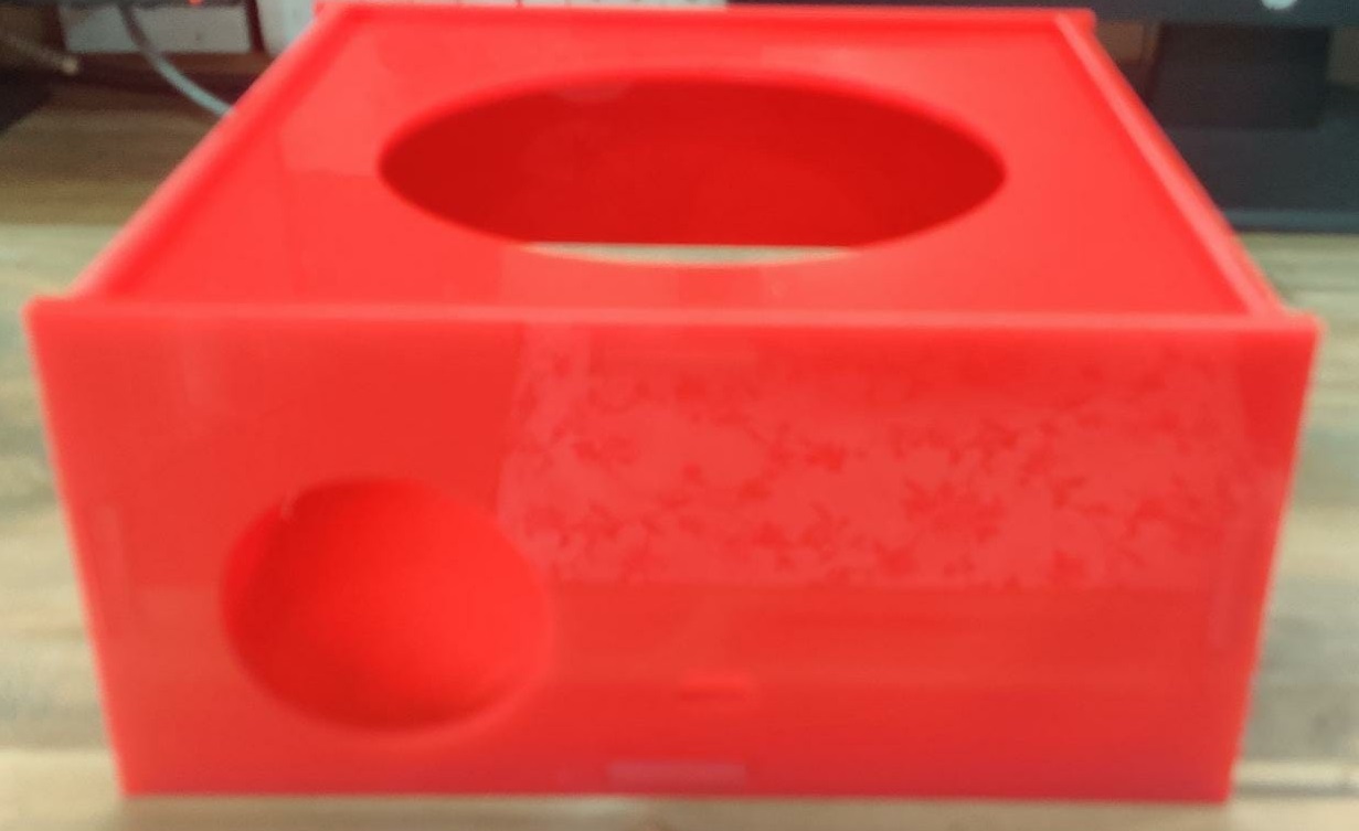
Assembled Box
This is the press fit box for keeping electronics.
Assembly of Tracker
I am assembling the parts of tracker.
 \
\
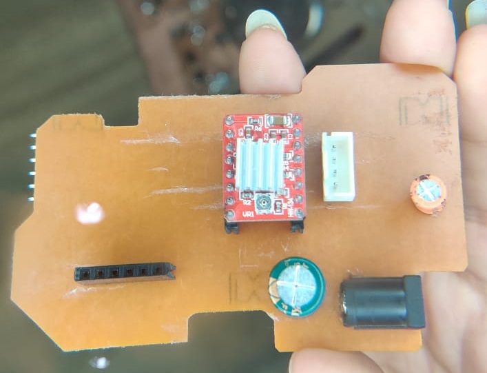
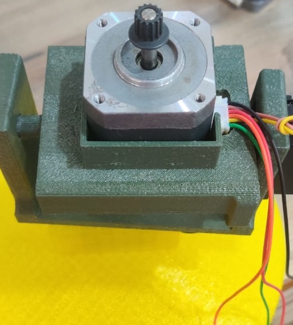
This is the stepper motor set in the box.
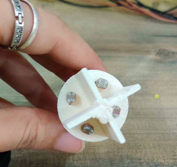
These are the LDR which will be mount on the head of flower.
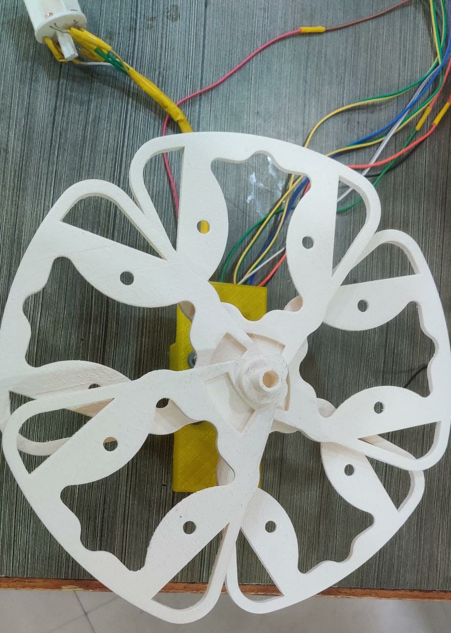
These are the petals in open position.
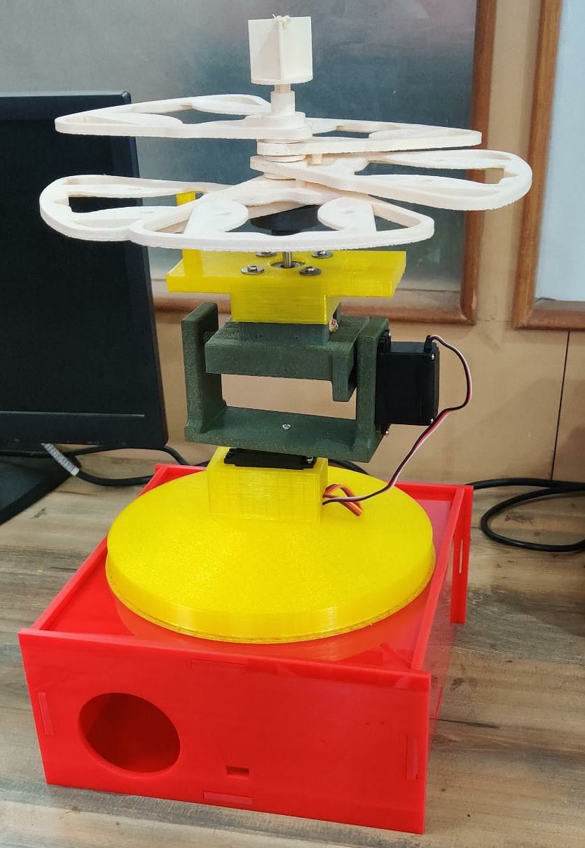
This is the half assembled tracker.
Testing of Servo
Here is the video showing the working of tracker.
Programming:
Here is the code for Servo motor to rotate with LDR.
    #include "Servo.h"
    #include "SoftwareSerial.h"
    #define RX   4   //TX pin of ATmega
    #define TX    3  //RX pin of ATmega
    SoftwareSerial mySerial(4,3);  //RX, TX

    // 180 horizontal MAX
    Servo horizontal; // horizontal servo
    int servoh = 90;   // 90;     // stand horizontal servo

    int servohLimitHigh = 180;
    int servohLimitLow = 90;

    // 65 degrees MAX
    Servo vertical;   // vertical servo
    int servov = 0;    //   90;     // stand vertical servo

    int servovLimitHigh = 60;
    int servovLimitLow = 0;


    // LDR pin connections
    //  name  = analogpin;
    int ldrlt = A2; //LDR top left - BOTTOM LEFT    <--- BDG
    int ldrrt = A3; //LDR top rigt - BOTTOM RIGHT
    int ldrld = A4; //LDR down left - TOP LEFT
    int ldrrd = A5; //ldr down rigt - TOP RIGHT

    void setup()
    {
      mySerial.begin(9600);
    // servo connections
    // name.attacht(pin);
      horizontal.attach(5);
      vertical.attach(6);
      horizontal.write(90);
      delay(3000);
      vertical.write(0);
      delay(3000);
    }

    void loop()
    {
      int lt = analogRead(ldrlt); // top left
      int rt = analogRead(ldrrt); // top right
      int ld = analogRead(ldrld); // down left
      int rd = analogRead(ldrrd); // down rigt

      // int dtime = analogRead(4)/20; // read potentiometers
      // int tol = analogRead(5)/4;
      int dtime = 10;
      int tol = 50;

      int avt = (lt + rt) / 2; // average value top
      int avd = (ld + rd) / 2; // average value down
      int avl = (lt + ld) / 2; // average value left
      int avr = (rt + rd) / 2; // average value right

      int dvert = avt - avd; // check the diffirence of up and down
      int dhoriz = avl - avr;// check the diffirence og left and rigt


      mySerial.println(avt);
      serial.print(avt);
      mySerial.println(" ");
      serial.print(" ");
      mySerial.println(avd);
      serial.print(avd);
      mySerial.println(" ");
      serial.print(" ");
      mySerial.println(avl);
      serial.print(avl);
      mySerial.println(" ");
      serial.print(" ");
      mySerial.println(avr);
      serial.print(avr);
      mySerial.println("   ");
      serial.print("   ");
      mySerial.println(dtime);
      serial.print(dtime);
      mySerial.println("   ");
      serial.print("   ");
      mySerial.println(tol);
      serial.print(tol);
      mySerial.println(" ");
      serial.print(" ");


      if (-1*tol > dvert || dvert > tol) // check if the diffirence is in the tolerance else change vertical angle
      {
      if (avt > avd)
      {
        servov = ++servov;
         if (servov > servovLimitHigh)
         {
          servov = servovLimitHigh;
         }
      }
      else if (avt < avd)
      {
        servov= --servov;
        if (servov < servovLimitLow)
      {
        servov = servovLimitLow;
      }
      }
      vertical.write(servov);
      }

      if (-1*tol > dhoriz || dhoriz > tol) // check if the diffirence is in the tolerance else change horizontal angle
      {
      if (avl > avr)
      {
        servoh = --servoh;
        if (servoh < servohLimitLow)
        {
        servoh = servohLimitLow;
        }
      }
      else if (avl < avr)
      {
        servoh = ++servoh;
         if (servoh > servohLimitHigh)
         {
         servoh = servohLimitHigh;
         }
      }
      else if (avl = avr)
      {
        // nothing
      }
      horizontal.write(servoh);
      }
       delay(10);

    }
I used this Tutorial for coding and I cahnged the value of variables used to move tracker in desired direction.
Here is the code for RTC and Stepper motor
    #include "Wire.h" //wire.h library
    #include "RTClib.h"


    RTC_DS3231 rtc;

    char daysOfTheWeek[7][12] = {"Sunday", "Monday", "Tuesday", "Wednesday", "Thursday", "Friday", "Saturday"};

    int x;


    int morningAlarmTimeHour = 08;
    int morningAlarmTimeMinute = 00;

    int eveningAlarmTimeHour = 18;
    int eveningAlarmTimeMinute = 0;

    DateTime alarmTime ;

    void setup ()
    {

      delay(3000); // wait for console opening

      if (! rtc.begin()) {

        while (1);
      }

      if (rtc.lostPower()) {

        rtc.adjust(DateTime(F(__DATE__), F(__TIME__)));
      }

      pinMode(11,OUTPUT); // Enable
      pinMode(5,OUTPUT); // Step
      pinMode(6,OUTPUT); // Dir
      digitalWrite(6,LOW); // Set Enable low

    }

    void loop ()
    {
        DateTime now = rtc.now();

        int currentTimeHour = now.hour();
        int currentTimeMinute = now.minute();


        if(morningAlarmTimeHour == currentTimeHour && morningAlarmTimeMinute == currentTimeMinute ){
          //this is where the code for morning run should be added

          digitalWrite(11,LOW); // Set Enable low
          digitalWrite(6,HIGH); // Set Dir high

          for(x = 0; x < 200; x++) // Loop 200 times
            {
              digitalWrite(5,HIGH); // Output high
              delay(1); // Wait
              digitalWrite(5,LOW); // Output low
              delay(1); // Wait
            }
          }
        else if(eveningAlarmTimeHour == currentTimeHour && eveningAlarmTimeMinute == currentTimeMinute){
          //this is where the code for evening run should be added

          digitalWrite(11,LOW); // Set Enable low
          digitalWrite(6,LOW); // Set Dir LOigh

          for(x = 0; x < 200; x++) // Loop 200 times
            {
              digitalWrite(5,HIGH); // Output high
              delay(1); // Wait
              digitalWrite(5,LOW); // Output low
              delay(1); // Wait
             }
          }


        delay(1000);
    }
In this code as the current time will be the time which I defined already as morning time,the stepper motor moves in clockwise direction one revolution and if the current time according to real time clock module is evening time it will rotate the motor in anticlockwise direction.
Note : Library for ds3231 I have searched in manage library option of Arduino ide and installed from only there.
Packaging
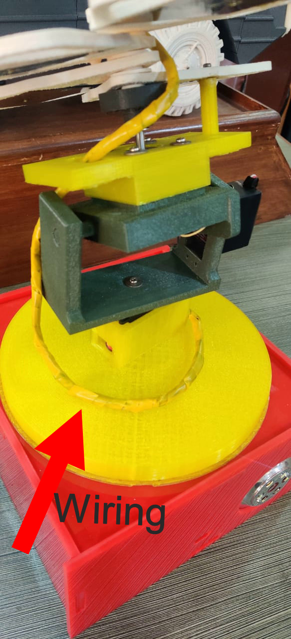
I tape all the wiring outside it with yellow tape .I need to implement it in design to stack the wiring but didnot do.So that why for packaging I used tape.
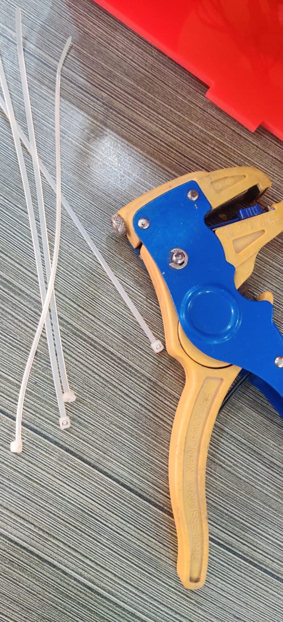
I used wire zipper to stack the wire inside the box with PCB
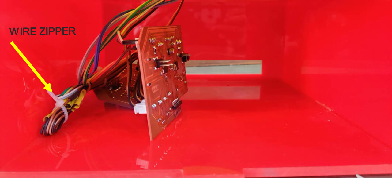
This is the stacking of wires with zipper.
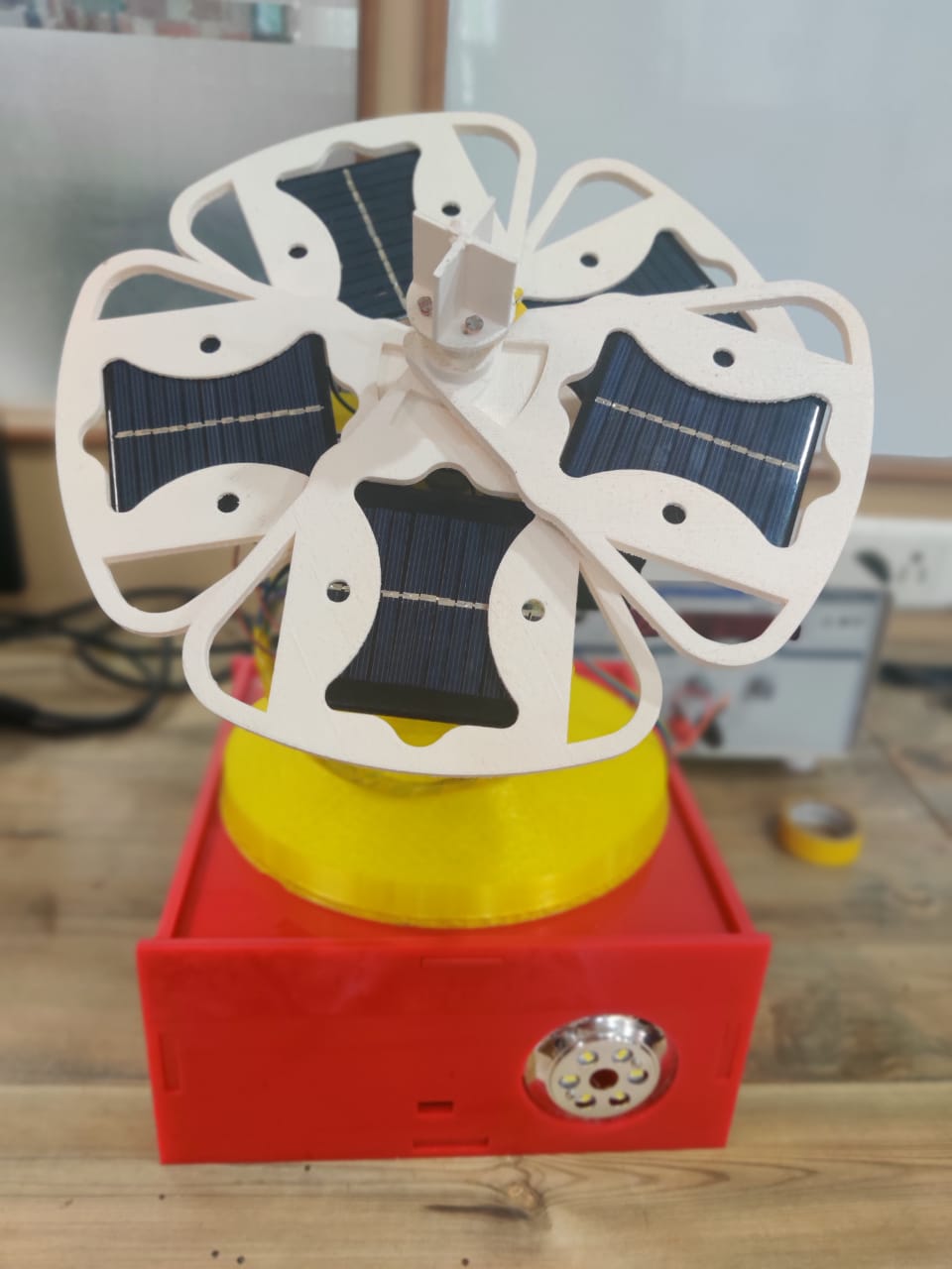
This is the final result of Smart sunflower solar tracker.
Conclusion:
I made my project with the main idea I was thinking to make.I learned lot of things mainly there were so many iterations of electronic design and production which I did.Before final presentation there was some problem occured with my stepper motor and its driver so the secondary function of moving petals not recorded.As well I did not produce any power with solar panels . In future I will work on it.